|
| ||||
|
--------------------------------------Animation Speed--------------------------------------
| ||||
 | ||||
|
--------------------------------------Animation Speed--------------------------------------
| ||||
 | ||||
|
| ||
 | ||
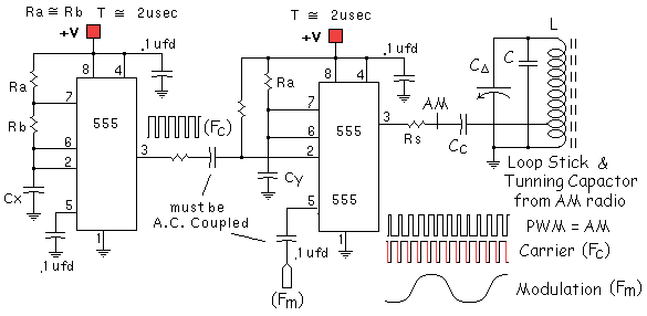
| A Word or Two about using Modulation for AM
broadcasting: Always keep the Pulse Width of the modulation between OR between > 00% & < 50%. At first blush, the reasoning for this may not be obvious: A transmitter is not broadcasting a varying voltage but a varying POWER. That is, the varying modulation voltage is controlling how much Carrier POWER is transmitted. Although the modulating voltage may have a polarity +/-, the RF power leaving the antenna has no polarity. At the receiver the varying power is demodulated/ which is saying it is converted from a varying power to a varying voltage, and if you "AC Couple" the detector's output you again have a varying voltage that has a +/- polarity. --Huh? NOW! At this point you should not
have experienced an "Ah Ha!"
--yet.
Notice anything Funny? Right, the second harmonic of the modulation signal increases if the [ > 50%, < 50% ] rule is violated! | ||
|
| ||
| ||
| 5) Don't be shy about using
several NEW parts--you could have a BAD PART(s)!
This includes resistors and CAPACITORS. ** DO NOT use electrolytics for the timing caps (if at all possible)! 6) Check the DATA SHEET, you
may be using a resistor for Ra or Rb that 7) Pin 5--the Voltage Control
pin of a 555 timer must be A.C. coupled! 8) When troubleshooting, remember more than 80% of all problems could have been found using your EYES! "--gee, I didn't see that the power cord was out of the wall..." 9) To get the best performance from the 555 in question, use the highest allowable supply voltage--15Volts--the timing capacitor should be in the picofarads and the "R" the very minimum value: you should get better than 500 kHz to ~2MHz. 10) Bypass the device and use groundplanes---***NO PROTO_BOARD!!!
| ||
|
** MORE SUGGESTIONS: **
1) BYPASS pin 8 (Vcc) to 1 (grd.) with at least .1 ufd ceramic cap--shortest leads possible!!! 2) Use the smallest timing capacitor--pins 6&2 to grd. 3) Try different 555 chips,
and/or different manufacturers 555s they vary!
| ||
| Finally, Don't hesitate to "PLAY"--to experiment with this device; the 555 timer has many uses--some yet to be discovered; who knows you may be the one to find even more uses for it. |
|
| |
 |
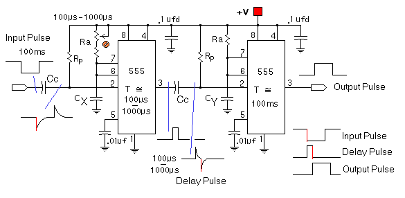
Triggering a
555 requires that the "Trigger" input be A.C. coupled. Typical
values can be found in the 555's data sheet & app
notes.
However, some values: Rp = 10k, Cc = .001ufd. |
| ______________ | |
 | |
|
|
|
| The timer receives pulses from the distributor points. Meter M receives a calibrated current thru R 6 when the timer output is high. After time-out, the meter receives no current for that part of the duty cycle. Integration of the variable duty cycle by the meter movement provides a visible indication of engine speed . | |
 |
|